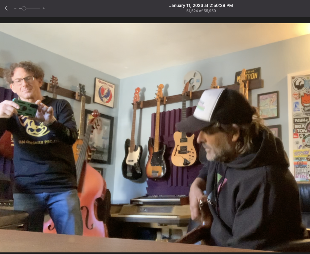
So some time had passed by , since the first episode with the Bass. I had run into Mr. X at a few concerts around town, and he was cruising around showing-off his bass and having people play it and such.
He wanted to bring it over to my studio and see if I wanted to record it again and show me all the tweaks that had been done.
He came over and I played the bass on a couple new songs I was writing. And then he said that he was going to work with a Luthier to build 10 replica basses to sell to dead head for $20000-$30000 a piece.
He had told me that Rick Turner’s daughter was going to design and build all this. He then stated, “I might need you help, I already paid her to build the electronics, but she blew me off. Can you do it? He was dropping lots of names and I was pretty much under the impression that Rick Turner was part of Alembic as was his daughter as of recent. This was all new to me. I had heard all these names but did not who did what for whom. I would later come to find that she had nothing to do with Alembic. So why did she have these schematics? Rick Turner had been at Alembic but only up to 1978.
I already knew I COULD build it, but I was way too busy doing what I was doing building our own products. But at the same time I was kind of blown away that Alembic did not want to do it and was willing to allow it and would send me the schematics.
First, I must explain the 4 parts that need get built.
1. The Super Filter was basically what we call an Active Filter or Variable State Filter. In the bass, It basically acts as a very surgical or “Parametric” EQ. It is a circuit employed in most of the products which we had been designing since 1972 or so. Alembic began to use this type of circuit as opposed to the standard passive EQ. In this case, there are two, one dedicated for each pickup. Alembic had actually made this into a rack mount product which had become rare and expensive on the used/vintage market. For many years prior, we had customers ask us to build them one in a pedal format. I was very familiar with this circuit at this point as there many schematics and even clone builds that had occurred and which were floating around the internet. I really did think there was enough of a market for it, nor was it really our job to reissue alembic designs. Alembic wan’t going to do it either.
I had already found it online several years before online
https://www.freestompboxes.org/viewtopic.php?t=11458
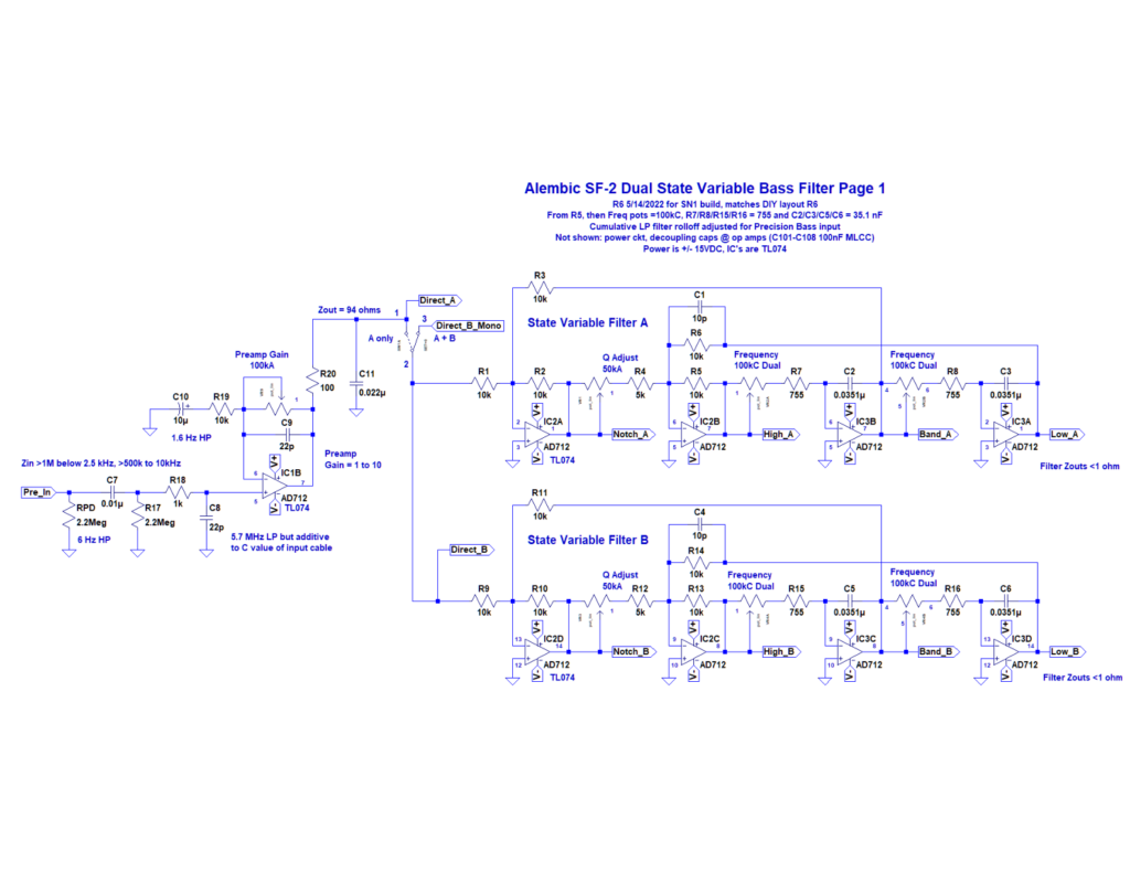
and even some successful clone pedal builds going down .
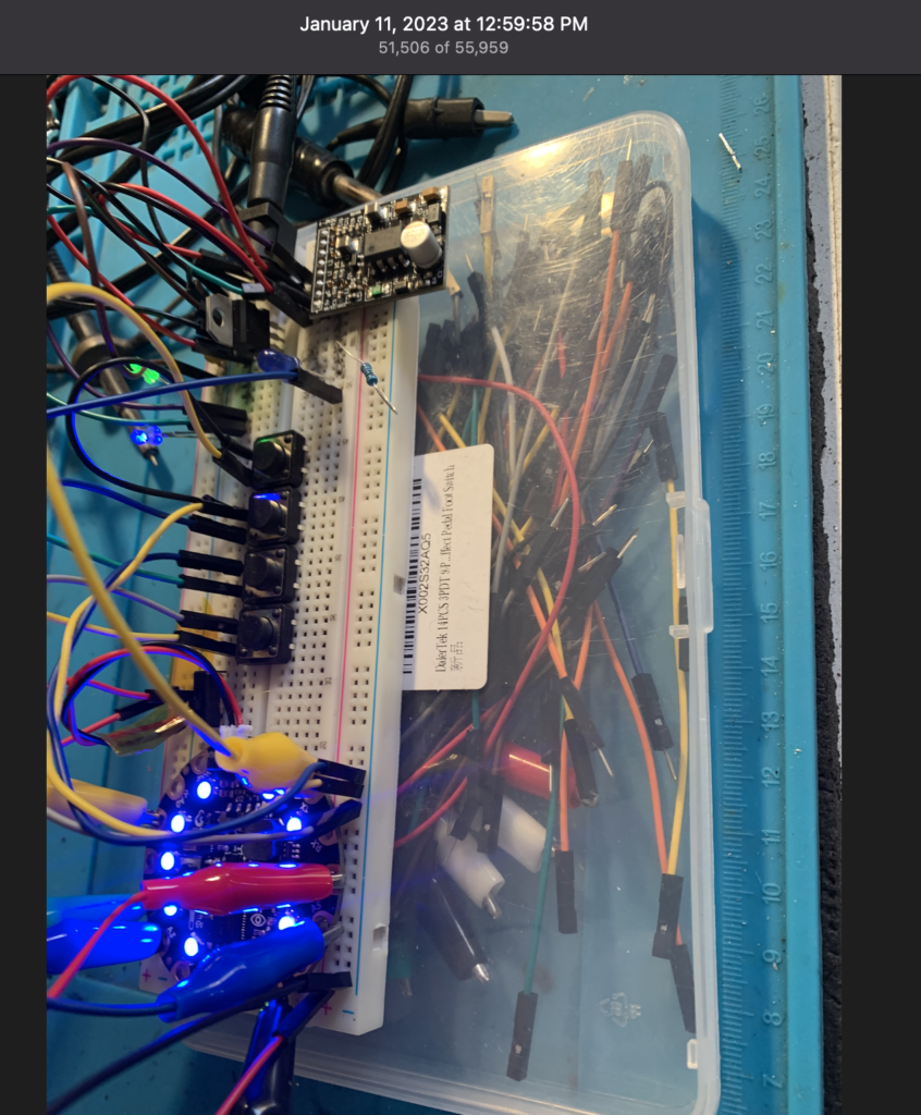
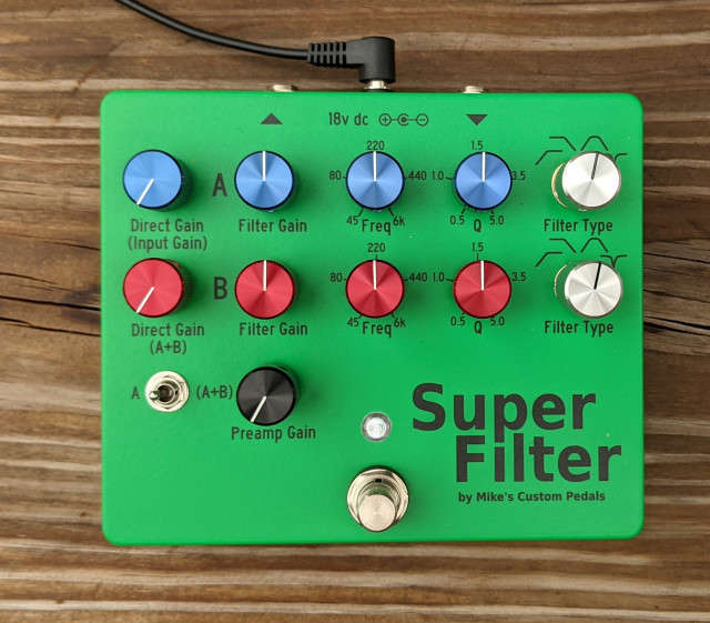
So I was like, I’ll do the Super Filter but only if I can build it in our format,
using SMT parts and the parts we use, and that I can make it a product and sell it under the Mu-Tron brand. I said I didn’t have the time to do thru-hole construction with NOS parts. But if I could do it in our factor ,
I could turn it around pretty quick. Like have a working prototype in a month. Mr. X said OK.
2. The QUAD preamp. The bass also has a split 4 way pickup where an element is dedicated to each string. Each pickup needed a preamp driver to boost the signal. This would allow for each string to be placed to different speakers or panned across the stereo field. In my mind there should be a way for the player to actuate presets to change the panning on the fly. That was not the case of the original OR it was just never realized.. To me, the QUAD was a pretty simple circuit and I knew I could get it done quick if I built it same as the Super Filters. I know I couldn’t productize this but I said OK I’ll do the QUAD.
3. LED light system driver which would illuminate 11 or so LEDS in the body and 13 or so in the neck. In the 1970s LEDs were pretty much green or red. So next to each LED was a button which would allow for the LED to be green, red, or off. The neck LEDs were just red and could only be on or Off. In my mind these would have been the “panning presets” that were never flushed out. They would have most likely required relays in 1976. I will never know. Any way he just wanted the Red/Green/Off. This was bag of worms. I knew I could, but this would take the most of my time. Usually, If you walk into your corner “”Design “Electronics-R-US” this would cost $10000 at least. I said NO I don’t want to touch this. Ironically, I had been doing a bunch of tinkering with micro-controllers and digital LEDS . It was still a hard NO!
4. “Breakout” box to interface to the other end of the 10 pin LIMO cable. It would provide 18volt power from the wall and 6 audio jacks for the 4 QUAD feeds and the 2 Super Filter feeds. I said NO I don’t want to touch this. He said how are you gonna power it. I said both the Super-Filter and the QUAD can both run on the power supply we already manufacture and it could even power the LEDS. if their current draw is not too high. That’s pretty much for free and all I will need is a 9volt rail of the LIMO and a ground. Heck you could put a battery in it. Then he says “I don’t care about how it gets done, I just need it done:”